What is a Real Time Clock? RTC Module Mechanisms and Uses
Real time clocks (RTCs) are essential for the innumerable applications out there that require accurate timekeeping. Furthermore, RTCs do more than just keep track of time. Epson's modularized RTCs in particular integrate key components, reducing power consumption and, with fewer external components, simplifying implementation and layout.
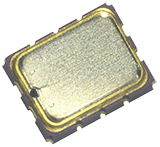
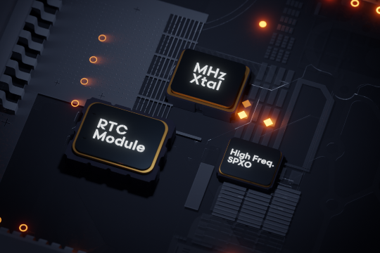
RTC Module
(3.2mm × 2.5mm package)
Overview of Real Time Clocks (RTC)
What is a real time clock (RTC)?
An RTC (Real Time Clock) is a dedicated IC that generates and outputs time, date, and other digital data from a clock source. It may also refer to functional blocks and software that realize these same functions.
How do real time clocks (RTC) work?
A basic RTC consists of a crystal unit as a clock source, its oscillator circuit, and a date/time counter circuit. Applying a voltage to the crystal produces a phenomenon called the "piezoelectric effect,” generating a small electric charge. This electric charge is amplified and fed back to the crystal to obtain a constant frequency signal. The oscillation signal of the crystal unit is used as the clock source of the date-time counter circuit to generate date-time data. Quartz crystals have the most stable oscillation frequencies among all piezoelectric materials and therefore generate highly accurate time data.
What are Real Time Clock Modules (RTC Modules)?
What is an RTC module?
RTC functions can be embedded in an MCU, but you can also use either a separate RTC module or a discrete RTC (called an RTC IC or RTC chip). Separating the RTC from the MCU allows the time to be kept independently, even when the MCU is in Sleep mode. As explained below, RTC modules have crucial advantages over discrete RTCs.
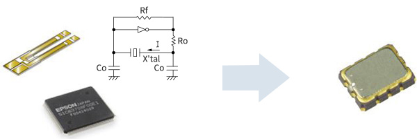
An RTC module is a single package that contains an integrated RTC IC, oscillator circuit, and master clock.
Differences between an RTC module and an RTC IC
Unlike RTC ICs, RTC modules contain the necessary components in a single-package, so users don’t have to design their own oscillator circuits or make frequency adjustments.
RTC modules can save board space, since they reduce the number of discrete components. They also have the advantage of being less susceptible to influence from the external environment.
Three configurations that provide RTC functions and the features of each
| (1) MCU with a built-in RTC | (2) RTC IC | (3) RTC Module | |
|---|---|---|---|
| RTC Solution | 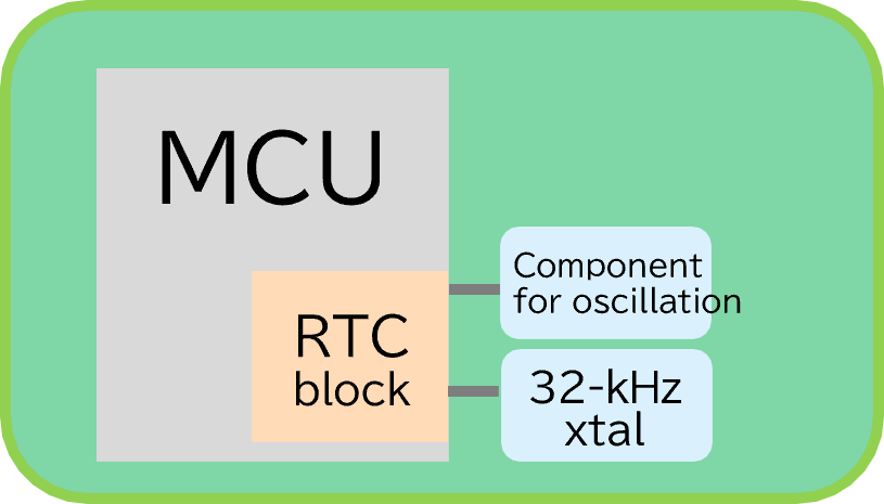 |
 |
 |
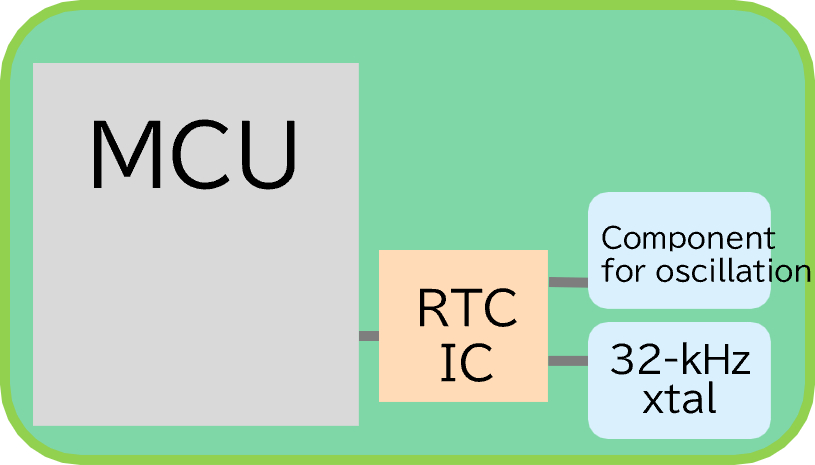
| PCB Layout | 1: MCU 2: 32-kHz Crystal 3: Component for oscillation |
1: MCU 2: RTC IC 3: 32-kHz Crystal 4: Component for oscillation |
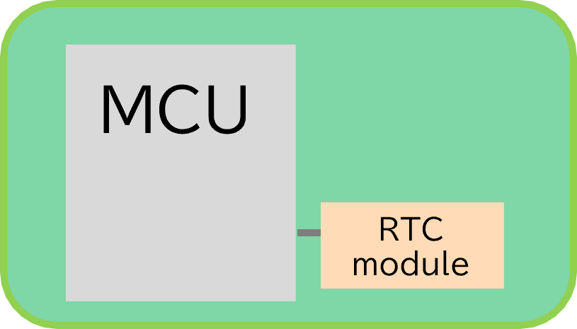
1: MCU 2: RTC Module |
| Circuit design | 1: Require verification for each part change 2: Designing built-in temperature compensation can be challenging 3: Mass production quality must be ensured, considering variations in the characteristics of each component. |
No required | |
Main uses of RTC modules
Even when the MCU is in sleep mode, an RTC module can continue timekeeping and wake the MCU up at a specified interval or any designated time using its wake-up timer or alarm. This allows the MCU’s active time to be minimized, leading to significant reductions in overall system power consumption.
- Examples of use : MFP (Multifunction Peripheral), Automotive BMS (Battery Management System), etc.
Due to superior timekeeping precision, these models are widely adopted in applications where minimizing time drift is critical or where periodic time synchronization with a server is not possible.
- Examples of use : Infortainment, Smart Lighting, etc.

High Accuracy and Low Current Consumption! Epson's RTC Module Uses a Quartz Crystal Unit
Overview of Epson's RTC modules
Epson's RTC modules are a single-package solution that combines an RTC IC, which is equipped with an oscillator circuit and date-time counter, with a crystal unit that has been optimally designed for it.
Epson fabricates its own quartz crystals and ICs, ensuring that its RTC modules provide high accuracy and low current consumption. These modules can reduce power consumption and increase efficiency in systems with a variety of features and functions.
Features of Epson's RTC modules
- The single-chip integrated design saves and eliminates the need for a power supply switching circuit.
- Temperature compensation limits frequency drift to within ±9 seconds per month. *Limited XA accuracy product (-40℃ to +105℃ environment)
- Reduce power consumption in Sleep mode.
- No circuit matching required, saving time and work.
- Lineup automoive products
Epson's RTC Module Product Lineup
We offer an extensive lineup of products through a combination of basic and optional features and functions.
Basic features on all models:


Type1 Normal Stability
| Model | Characteristics | Voltage Range [V] |
Frequency Temperature Characteristic |
Operating Temperature [℃] |
Backup Current [μA] |
Feature | ||
|---|---|---|---|---|---|---|---|---|
| Frequency Tolerance [x10-6] |
Condition [℃] |
|||||||
|
RX8130CE
BriefSheet |
Ideal for efficient use of backup batteries |
1.1 to 5.5 | 5±23 | +25 | -40 to +85 | 0.3 |
|
|
|
I²C-Bus RX8111CE BriefSheet |
SPI-Bus RX4111CE BriefSheet |
Lowest current consumption |
1.1 to 5.5 | ±11.5 | +25 | -40 to +105 | 0.1 |
|
| ±23.0 | +25 | |||||||


Type2 High Stability
| Model | Characteristics | Voltage Range [V] |
Frequency Temperature Characteristic |
Operating Temperature [℃] |
Backup Current [μA] |
Feature | ||
|---|---|---|---|---|---|---|---|---|
| Frequency Tolerance [x10-6] |
Condition [℃] |
|||||||
|
RX8900CE
BriefSheet |
When all you need is accuracy! Simple temperature compensation |
1.6 to 5.5 | ±3.4 | -40 to +85 | -40 to +85 | 0.7 |
|
|
| ±5.0 | -40 to +85 | |||||||
| ±5.0 | -30 to +70 | |||||||
|
RX8804CE
BriefSheet |
Works even in high temperature environments |
1.5 to 5.5 | ±3.4 | -40 to +85 | -40 to +105 | 0.35 |
|
|
| ±8.0 | +80 to +105 | |||||||
| ±5.0 | -40 to +85 | |||||||
| ±8.0 | +80 to +105 | |||||||
|
I²C-Bus RX8901CE BriefSheet |
SPI-Bus RX4901CE BriefSheet |
Equipped with nearly the full range of options |
1.1 to 5.5 | ±3.0 | -40 to +85 | -40 to +105 | 0.24 |
|
| ±5.0 | -40 to +105 | |||||||
| ±5.0 | -40 to +85 | |||||||
| ±8.0 | -40 to +105 | |||||||


Type3 Automotive
| Model | Characteristics | Voltage Range [V] |
Frequency Temperature Characteristic |
Operating Temperature [℃] |
Backup Current [μA] |
Feature | ||
|---|---|---|---|---|---|---|---|---|
| Frequency Tolerance [x10-6] |
Condition [℃] |
|||||||
|
RA8900CE
BriefSheet |
AEC-Q200 | 1.6 to 5.5 | ±3.4 | -40 to +85 | -40 to +85 | 0.7 |
|
|
| ±5.0 | -40 to +85 | |||||||
|
RA8804CE
BriefSheet |
AEC-Q100 | 1.1 to 5.5 | ±3.4 | -40 to +85 | -40 to +105 | 0.35 |
|
|
| ±8.0 | +85 to +105 | |||||||
| ±5.0 | -40 to +85 | |||||||
| ±8.0 | +85 to +105 | |||||||
|
I²C-Bus RA8000CE BriefSheet |
SPI-Bus RA4000CE BriefSheet |
AEC-Q100 | 1.3 to 5.5 | ±5.0 | -40 to +85 | -40 to +125 | 0.3 |
|
| ±8.0 | -40 to +105 | |||||||
| ±50.0 | -40 to +125 | |||||||