What is an Oscillator Circuit? The Basics, Mechanisms, and Principles, Simplified
What is an Oscillator Circuit?
What is an oscillator circuit?
An oscillator circuit is a circuit that continuously outputs an AC signal on its own. It consists of a feedback circuit, a resonant circuit, and an amplification circuit.
What is oscillation? crystal oscillator mechanisms and principles
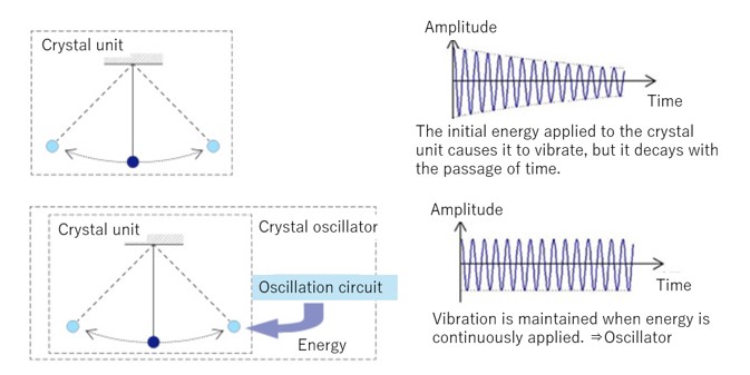
To cause a crystal unit to oscillate, a crystal oscillator needs to have an oscillator circuit that is matched to the characteristics of the crystal unit. The motion of a crystal unit is analogous to that of a pendulum. To cause a pendulum to continue swinging back and forth, you must detect the pendulum’s position and time of maximum swing and apply a force to constantly push the pendulum back to that position and time. The oscillator circuit is responsible for this detection and the force used to push the “pendulum” back at a constant energy.
Crystal Oscillator Principles
Oscillator Circuit Oscillation Conditions and a Sample Circuit Diagram
A crystal unit is represented by an equivalent circuit and is expressed using effective inductance (Le) and effective resistance (Re). On the oscillator circuit side, they are replaced by an equivalent circuit with load capacitance (CL) and negative resistance (-RN). The oscillation conditions are as follows:
ΩLe = 1/(ΩCL)
Re ≦ |-RN|
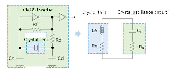
Sample Circuit Diagram
How to determine the load capacitance (CL)
CL= (Cg x Cd) / (Cg + Cd) + Cs
The load capacitance of the oscillator circuit is the total capacitance, not just Cg and Cd. The stray capacitance of the board and the internal capacitance of the IC (Cs) must also be considered. For example, if both Cg and Cd are 20 pF, CL is not 10 pF.
How to determine negative resistance (|-RN)
-RN = -gm / (Ω2 x Cg x Cd)
While oscillation will occur if the oscillation condition Re = negative resistance (−RN) is met, it is not sufficient on its own.
Oscillation margin = |-RN|/Re ≧ 5 (10)
It is recommended to ensure an oscillation margin of at least 5 times Re, and for automotive applications, at least 10 times.
Important Considerations for Oscillator Circuits
There are three key considerations when designing an oscillator circuit.
(1) Oscillation frequency
(2) Negative resistance
(3) Drive level
(1) How to determine oscillation frequency
dF/F = C1/2 x (CL + C0)
The graph below shows the relationship between load capacitance and oscillation frequency.
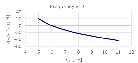
Determining Oscillation Frequency
When the value of the negative resistance changes, the oscillation frequency also changes. If the load capacitance on the crystal unit side does not match the load capacitance on the oscillator circuit side, the oscillation frequency will shift. For example, in a crystal unit with the above characteristics, a change of 1 pF in negative resistance results in a frequency change of 20 ppm. The curve of the graph above varies with the size and frequency of the crystal unit.
(2) How to determine negative resistance
Insert a resistor in series with the crystal unit and check whether oscillation occurs. By changing the resistance value as shown in the diagram below, you can determine the precise value at which oscillation stabilizes.
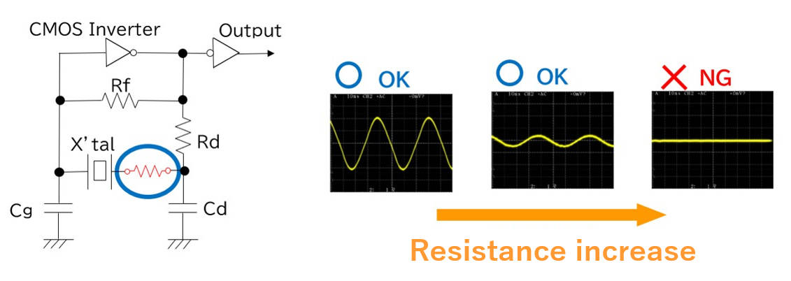
Determining Negative Resistance
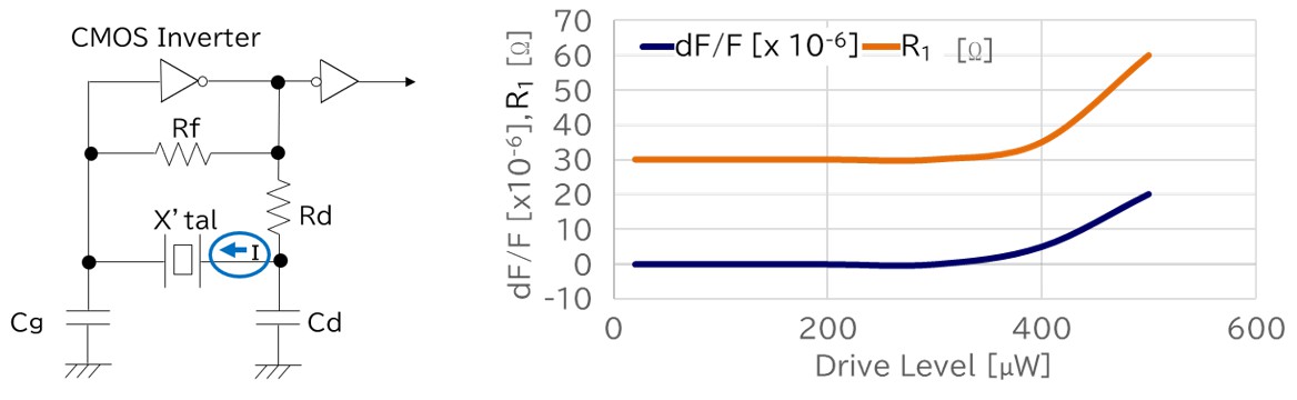
(3) How to determine drive level
Measure the current flowing through the crystal to calculate the drive level. The drive level can be determined using the following formula:
Drive level (P) = I2 x Re
Re=R1 x (1+Co/CL)2
The current (I) flowing through the crystal unit is measured with a current probe. Re is the effective resistance of the crystal unit. Note that if the drive level is too high, the oscillation frequency will shift or the series resistance will increase. For this reason, it is recommended to use the drive level within the specification values listed in the data sheet.
Determining Drive Level
Output Waveform of a Crystal Oscillator and Its Measurement Circuit
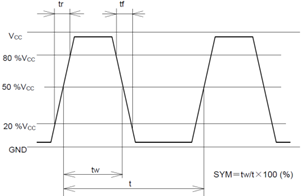
Output waveform of a crystal oscillator
The figure on the right depicts an output waveform and measurement level.
Measurement conditions
(1) Oscilloscope
- The measurement bandwidth of the oscilloscope should be at least 5 times the frequency of the oscillator being measured.
- Connect the probe's ground (GND) as close as possible to the measurement signal extraction point, and keep the GND wiring as short as possible.
Note: A fixture with a short GND wire, such as a miniature socket, is recommended.
(Do not use a GND lead wire.)
(2) L_CMOS (output load capacitance)
Include the capacitance of the probe.
(3) Bypass capacitor
Use a capacitor between 0.01 μF and 0.1 μF, and place it as close as possible to the Vcc and GND of the oscillator.
(4) Ammeter
Use one with a low internal impedance.
(5) Power supply
- The rise time from 0 V to 90% Vcc should be at least 150 μs.
- Keep the impedance of the power supply as low as possible. The GND wire should be as short as possible.
Examples of Oscillator Circuit Use and Applications
Oscillator circuits are used as frequency signal sources in communication equipment, industrial equipment, and automotive equipment, as timing clocks in watches, and as clock sources in digital circuits.
Features of Epson’s Crystal Oscillators
Epson’s crystal oscillators are divided into several types depending on their configuration and accuracy.
Simple packaged crystal oscillators (SPXOs), and their features and applications
An SPXO is a type of crystal oscillator that provides stable frequency output without temperature compensation or temperature control. Housing an oscillator circuit along with either an AT-cut crystal unit or a tuning fork crystal unit in the same package, an SPXO is designed and manufactured to output a stable signal when a specified supply voltage is applied to it. Typical accuracy ranges from ±20 to ±100 ppm depending on the temperature range. These oscillators are used in a variety of applications and markets.
Temperature compensated crystal oscillators (TCXOs), and their features and applications
A TCXO is a temperature-compensated crystal oscillator designed to enhance frequency stability by incorporating a temperature compensation circuit. This circuit makes it less susceptible to external environmental temperature changes, resulting in greater accuracy than an SPXO. Generally, the accuracy is at the level of a few ppm. TCXOs are often used for reference signals in wireless communications and in network applications.
Voltage-controlled crystal oscillators (VCXOs), and their features and applications
A VCXO is a voltage-controlled crystal oscillator that includes a voltage-controlled variable reactance element, such as a varactor diode, in its oscillation loop. This allows the output frequency to be adjusted according to the set voltage. VCXOs are increasingly used as slave oscillators in phase-locked loops (PLLs) and as frequency modulators. A crystal oscillator that combines a VCXO and TCXO is called a VC-TCXO. These have the advantage of allowing fine frequency adjustments electrically. The absolute variable range of a VCXO is generally 50 ppm, while the absolute variable range of a VC-TCXO is at the level of a few ppm.
Programmable crystal oscillators, and their features and applications
A programmable crystal oscillator is an oscillator with a PLL circuit. As the name suggests, it can be programmed to output a desired frequency. The programmability means that these oscillators can be acquired with a shorter lead time than oscillators written with common output frequencies.
Features of Epson’s programmable oscillators
Epson has two main types of programmable oscillators.
1) Programmable oscillators
These crystal oscillators can be programmed, allowing for short lead times, small lot sizes, and support for non-standard frequencies. A dedicated tool is used to write any output frequency. Our programmable oscillators, and those in our SG-8101 series, in particular, incorporate an Epson IC and are accurate within ±15 ppm. Please see the links to the product pages below for details.
| Size | General Purpose | High Accuracy | Automotive |
|---|---|---|---|
| 2.0 x 1.6 mm | SG-8200CJ | SG-8201CJ | SG-8201CJA |
| 2.5 x 2.0 mm | SG-8200CG SG-8018CG | SG-8101CG SG-8201CG | SG-8101CGA |
| 3.2 x 2.5 mm | SG-8018CE | SG-8101CE | |
| 5.0 x 3.2 mm | SG-8018CB | SG-8101CB | |
| 7.0 x 5.0 mm | SG-8018CA | SG-8101CA |
2) Programmable oscillators with spectrum spread function
In addition to the basic functions of programmable oscillators, Epson offers a series of programmable oscillators with a spread spectrum function. This function is effective as a countermeasure against electromagnetic noise. By modulating the frequency over a specific frequency domain relative to the output frequency, this feature can suppress the peaks of the fundamental wave and harmonics spectrum, thereby reducing EMI. These oscillators can also be purchased with short lead times and in small quantities, making them suitable for cases where specific non-standard frequencies are needed or during prototyping. Please see the links to the product pages below for details.
| Size | General Purpose | Automotive |
|---|---|---|
| 2.5 x 2.0 mm | SG-9101CG | SG-9101CGA |
| 3.2 x 2.5 mm | SG-9101CE | |
| 5.0 x 3.2 mm | SG-9101CB | |
| 7.0 x 5.0 mm | SG-9101CA |